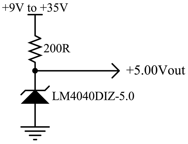
Build A Precision Voltage Reference Box Circuit Diagram The following schematic depicts the poor man's precision voltage reference circuit (10.0V ±0.3%). The 1N5819 Schottky diode (D1) is placed along the power supply to avoid damaging the voltage reference chip should the power polarity be reversed. The RC low pass filter (R1-C1) is optional but it can scale down the noise from the power supply. The input voltage range is 12V to 36VDC. In this video, I have shared how you can build a precision voltage reference that can output 0 - 4995 mV with a resolution of 1mV. How does one go about accurately setting reference voltages at various points in a given circuit (e.g. various threshold voltages). Obviously we can have a potential divider from the main power supply but that generally tends to fluctuate a lot, not to mention noise from other parts of the circuit. I would assume a sort of single voltage reference from which we can derive the rest of the
Phase 3: Build a professional proto The custom PCB version will be powered by battery as that will be desired. A boost converter for DAC voltage reference input and constant current circuit to work. I will also add isolated USB interface so that we can control the voltage current reference via PC. Display will be changed from OLED to a low power glass display which will consume 200-330uA while
️ DIY Precision Voltage Reference Circuit Diagram
The real magic happens in the Texas Instruments REF102 precision voltage reference. You give it a decently clean 12-36 volts, and it will give you a 10 volt reference out. This video gives a step-by-step demonstration of an amplifier and precision reference based circuit design for a relatively inexpensive precision voltage source. This type of diode is widely found in the manufacture of voltage references from diodes to precision, for electronics circuits and systems needing a regulated output, such as in power supplies.
Other possible reasons include using one to calibrate your DMM, or to construct a precision voltage-to-frequency converter or current source. The applications for a precision reference fall into two general categories: instrument (DMM, DVM) calibration/accuracy verification, or as a circuit component, such as the reference for an A/D converter. The downside to a voltage reference is that it only generates a single voltage and has limited current output. I decided to design a circuit that could generate any voltage between zero volts and 10 volts in 0.1 volt increments; for example, 4.8 volts with a basic accuracy of 10 millivolts and an output current of 100 milliamps (or one ampere