Drone Flight Controller Circuit Diagram As this flight controller is meant to be integrated on the TPU stack, I've worked on the v2 design and on the board shape simultaneously to take into account integration, usability and layout constraints. The result is a board using the standard 30.5×30.5mm mounting pattern, but with several tabs to accomodate some special features:

These are used for rescue operation, delivery, surveillance, defense, medical and agricultural purposes, etc. The main advantages of drones are compact size and easy controlling. In this article, we will learn how to design the quad copter (drone) using KK2.1.5 flight controller with the help of motors, flight controller, and chassis. I wanted to control my drone from an Arduino because I wanted to take a step into the automation of my drone. There was the option of building a drone and using the Arduino as the Flight Controller, but then I would miss out on all of the advanced features that the more popular firmware, like Betaflight, provides.

Designing my own Flight Controller Circuit Diagram
Once the flight controller is calibrated, the pilot can then start flying the drone. To do this, the pilot will use the throttle channel to increase or decrease the speed of the drone's motors. The pitch channel is used to control the angle of the Drone. Circuit Diagram - ESP8266 Flight Controller
Flight controller - This integrated circuit (IC) serves as the brain of the drone, controlling the motors and stabilizing flight. Some options are STM32, Arduino, or Raspberry Pi Pico. Support ICs - May need additional ICs like motor drivers or sensors. Connectors. Battery connector - JST or XT30 are common LiPo battery connectors. There are often two voltage ranges described in the spec sheet of a flight controller, the first being the voltage input range of the flight controller itself (most operate at 5V nominal), and the second being the voltage input range of the main microprocessor's logic (ex 3.3V or 5V).Since the flight controller is a fairly integrated unit, you really only need to pay attention to the input
How To Create PCB For Drone Circuit Diagram
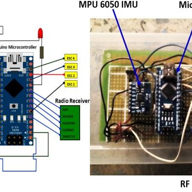
# How to Build a Flight Controller using a Microcontroller  and Acc (Accelerometer).
