Laser security system Circuit Diagram The laser based alarm system is suitable for application where detection based on light beam are useful. Similar alarm system can be designed using only LDR(see Light Dependent Resistor (LDR) Light Detector Alarm with Arduino). Other alarm system can be designed using Infrared sensor and/or Photo Diode(Photodiode Light Detector with Arduino).
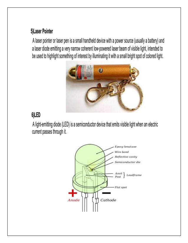
What is Arduino Laser Security System Alarm Project. To be simple it is just a security system that involves laser light. The laser diode used here gives out red light and is continuously made to fall on LDR. Place the laser diode first and use glue if necessary to keep it at an angle of 45 degrees.
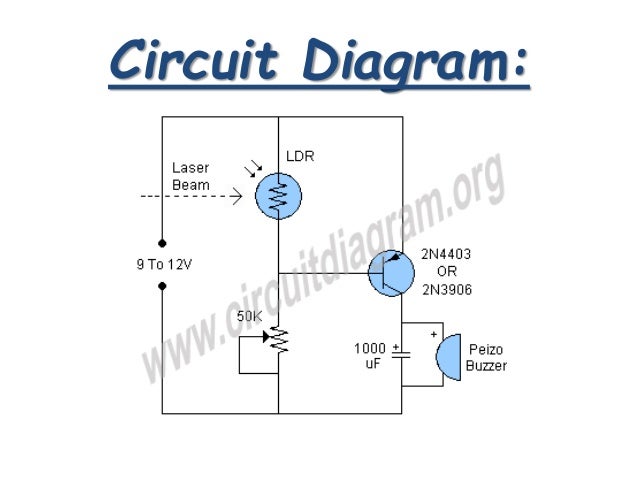
Simple Laser Security Alarm Using LDR Circuit Diagram
Tutorial to use Sensor First time!!In this video we are making a Laser Security System Alarm using LDR Module and Laser Diode Module . Link to code below. Lo
Here is a basic idea of how you can make a laser security alarm using an Arduino and an LDR sensor: Materials needed: Arduino board; Laser diode; LDR sensor; Buzzer; Breadboard; Jumper wires; 220 Ohm resistor; Steps: Connect the LDR sensor to the breadboard. Connect the 220 Ohm resistor to the LDR sensor and connect it to the ground pin on the
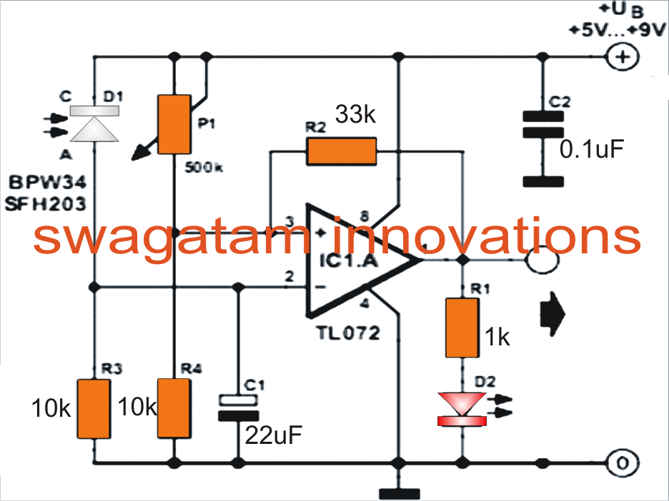
Laser Diode & LDR based alarm system using Arduino Circuit Diagram
When the laser pen shines on the photoresistor, the green LED will light up to signify that the circuit is ready. When the laser beam is broken, the LED turns off and the buzzer sounds. As we know from Projects 13 ("Weather Station") and 18 ("Intruder Sensor"), photoresistors produce variable resistance depending on the amount of light
